
Project Overview
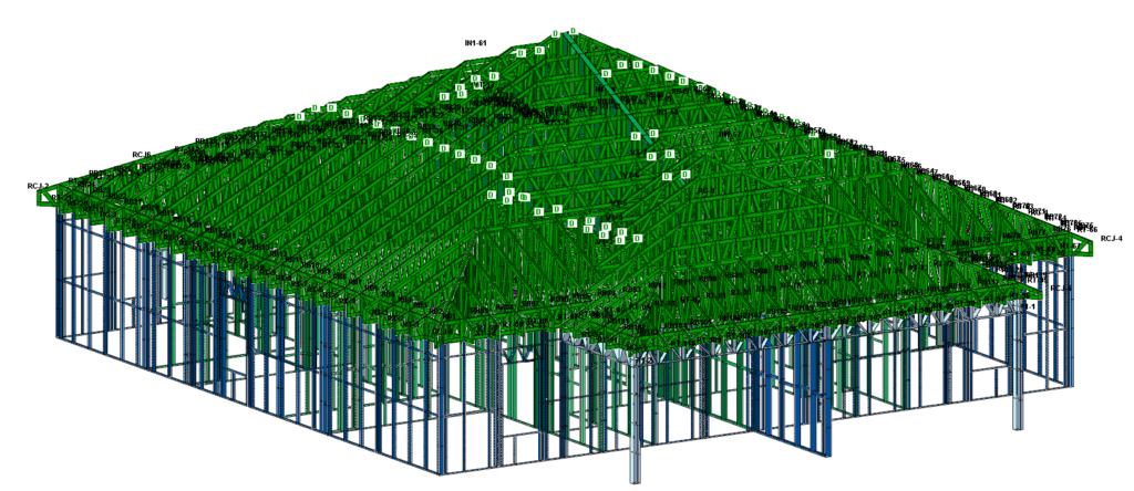
Residential Light Gauge Steel Home with hip roofs often present unique coordination and engineering challenges. Roof geometry directly influences the available attic space, framing configuration, and connection requirements.
This single-storey residential project in Los Angeles, USA of area 2,853 sq. ft. ,was designed with a light gauge steel framing using hip roof and Scope of work includes engineering, 3D modeling, detailing, and permit-set.
One of the key design considerations was the variation in available attic space. Changes in roof slope created different attic volumes across the building, making accurate roof geometry and framing coordination essential. Building information modelling services from LOD 100 to LOD 500 in USA for both light gauge steel and timber framed structures
Engineering Around Variable Attic Spaces
A hip roof does more than define the building’s appearance—it directly affects the structural framing and usable space below it.
Because the roof slopes and framing geometry change across the building, the available attic volume is not uniform. Accurate modeling helped establish the roof geometry and coordinate the framing around these changing conditions.
Through detailed 3D modeling, the roof framing could be reviewed digitally before fabrication or construction, helping ensure that the structural solution aligned with the architectural requirements.
Roof Truss Design
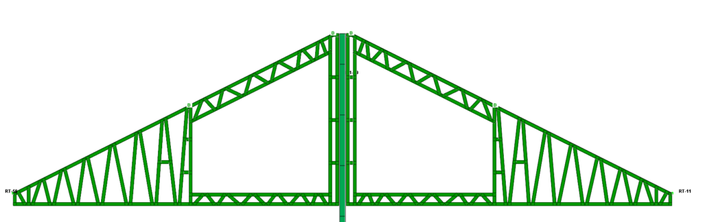
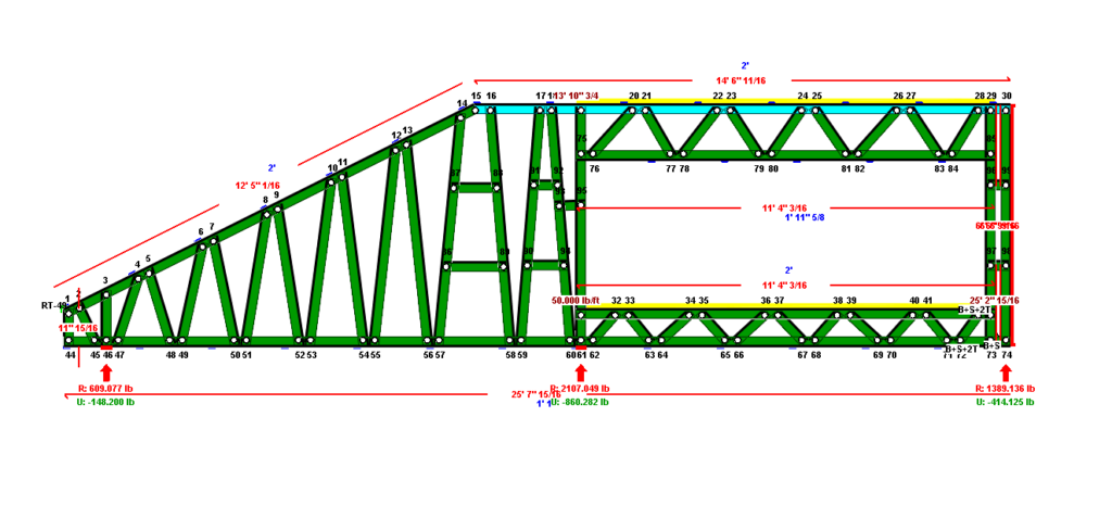
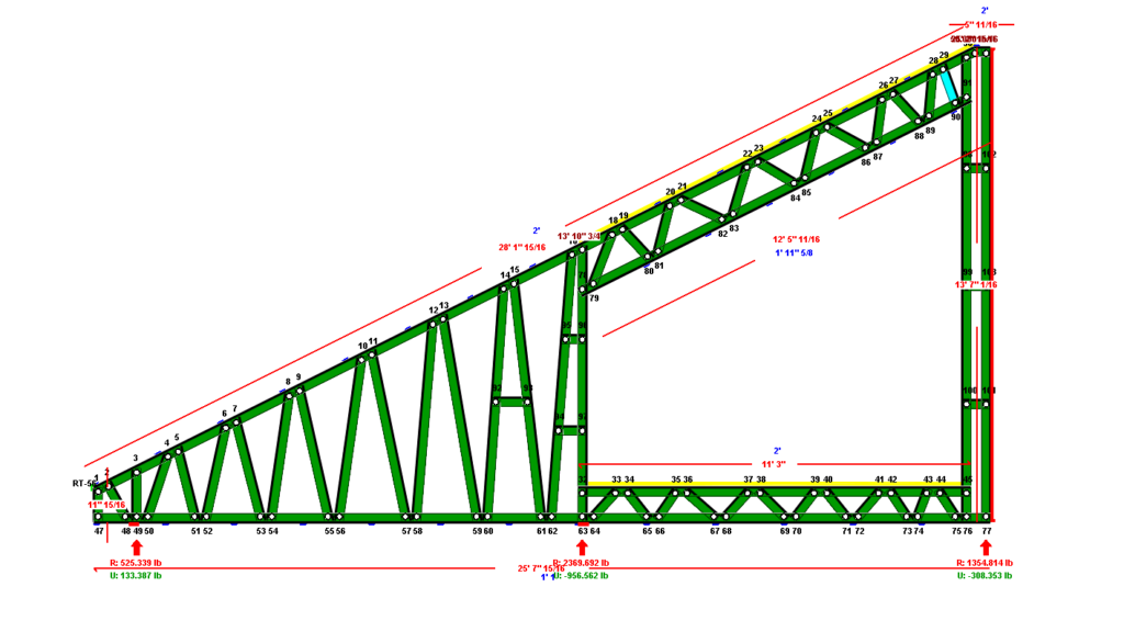
For the roof trusses, H3 / 1.5–43 50 ksi profiles were used to provide the required strength and durability for the project.
The truss design was developed around the project-specific structural requirements while maintaining accurate geometry for detailing and downstream fabrication.
This approach demonstrates the importance of connecting structural engineering with detailed BIM modeling—particularly when roof geometry and available attic space vary throughout a residential building.
Reliable Truss-to-Wall Connections
A structurally sound roof system depends not only on the trusses themselves but also on how those trusses connect to the supporting walls.
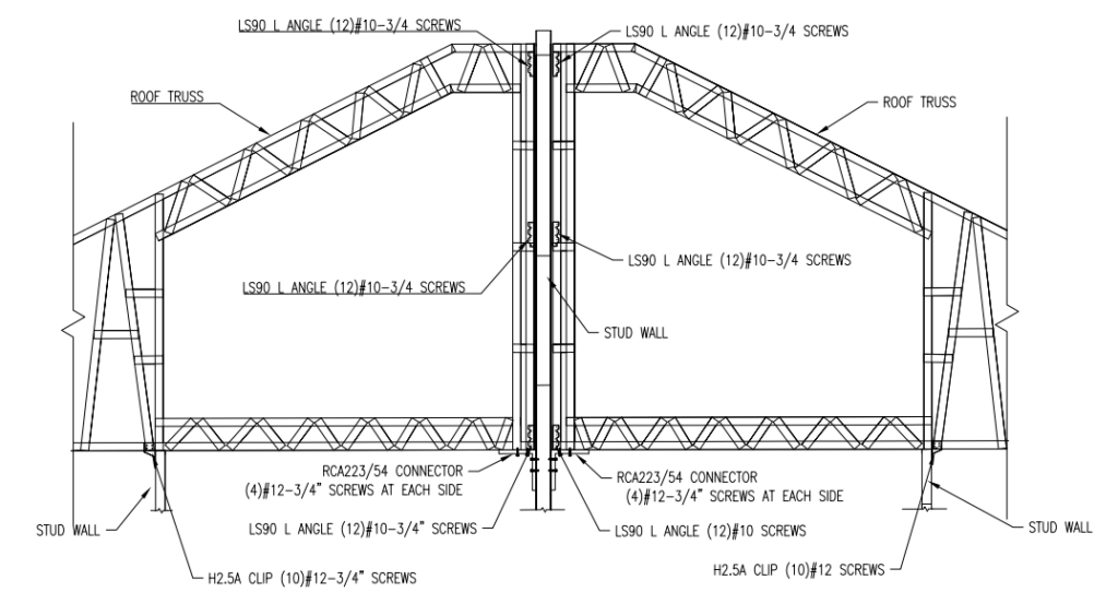
For this project, LS 90 and RCA 223 connectors were used for the truss-to-wall connections. These connections provided a consistent interface between the roof framing and wall system.
The connection strategy also supported the drywall system by maintaining continuity from the ground level through to the roof. This required careful coordination between the structural framing, connections, and architectural requirements.
Consistency Across the Reframe
The same connection approach was implemented for the mirror building reframe.
Maintaining a consistent connection strategy across both conditions helped simplify coordination while supporting structural stability and performance. It also reduced the risk of introducing unnecessary variations during detailing and construction.
The Role of BIM in the Process
This project highlights how BIM can connect engineering decisions with detailed construction information.
By developing the framing digitally, the team could coordinate:
- Roof geometry and varying attic volumes
- Roof truss configuration
- Truss-to-wall connections
- Drywall continuity
- Mirror-building reframe conditions
- Permit-set documentation
The result is a more coordinated workflow in which structural decisions can be reviewed and documented before they become construction issues.
Key Takeaway
A successful cold formed steel residential framing in USA, this solution is not simply about selecting the right structural members. It requires accurate engineering, coordinated modeling, detailed connections, and consistent documentation.
For this cold formed steel residential building in Los Angeles , the combination of H3 / 1.5–43 50 ksi roof-truss profiles, LS 90 and RCA 223 connections, detailed BIM coordination, and permit-sets helped create a reliable framing solution while addressing the challenges created by the hip-roof geometry and varying attic spaces. UBC offers permit sets, pre-bid packages with 3D BIM model along with bill of materials for project cost estimation, modelling and detailing services, engineering calculations for light gauge steel/cold formed steel/ timber framed building structures
At UBC BIM, the goal is to turn complex structural requirements into coordinated, fabrication-ready information—before construction begins.
How does BIM help with light gauge steel hip roof design?
BIM creates a coordinated 3D representation of the structural framing. It allows roof geometry, trusses, wall framing, connections, and architectural requirements to be reviewed and coordinated before fabrication or construction.
What roof truss profiles were used for this project?
The project used H3 / 1.5–43 50 ksi profiles for the roof trusses, designed according to the project's structural requirements and coordinated with the detailed framing model.
What connections were used for the roof trusses?
LS 90 and RCA 223 connectors were used for the truss-to-wall connections. These connections helped establish a consistent interface between the roof framing and supporting wall system.
Why is attic space important in a hip roof building?
The slopes and geometry of a hip roof can create different attic volumes throughout a building. Accurate roof and framing coordination helps identify these variations and ensures that the structural solution aligns with the architectural requirements.
