Modular building is changing how we think about high-quality housing. By building in a controlled environment and then moving the home to its final spot, we can create beautiful, strong, and affordable spaces.
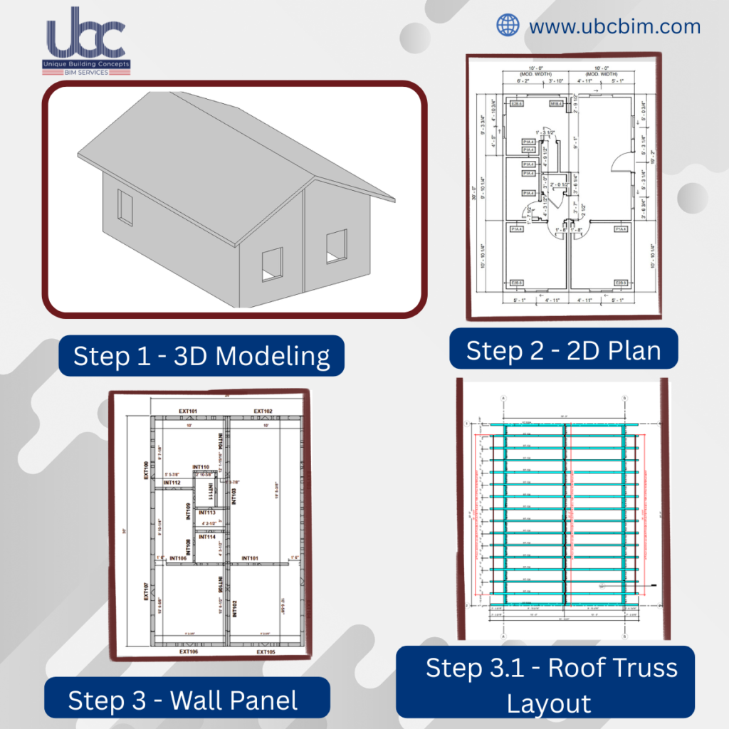
This project is a great example of how modern BIM engineering services for light gauge steel construction makes small-scale living feel high-end.By splitting a 600-sft area and 300 sft each module modular residential building in California ,USA, we’ve created a layout that is easy to transport but feels like a solid, permanent home once joined. Here are a few technical highlights that make this specific build stand out. Building information modelling services from LOD 100 to LOD 500 in USA for both light gauge steel and timber framed structures in California, USA
Scope of Work: Engineering
Permit sets
Foundation
CNC Foundation files
Here is why this smart design works so well
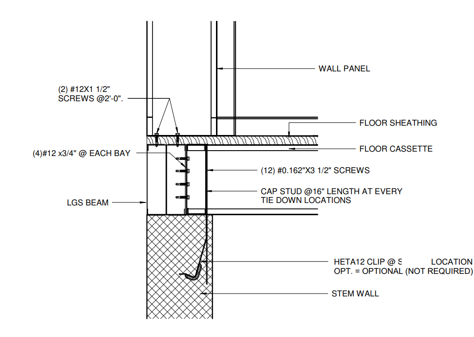
Stem Wall and Floor Beam Detail
1.Strength You Can Trust
Traditional homes use wood, which can warp or shrink. Instead, we use Light Gauge Steel for modular construction (LGS). For this project, we engineered a specialized floor system using steel beams and stem wall Foundation. This creates a rock-solid foundation that feels permanent and sturdy, even though the house was built in sections
2. Structural Rigidity & Load Path
By utilizing a concrete stem wall rather than isolated piers, we create a continuous bearing surface. This is critical for LGS engineering of modular building, as it allows for a uniform transfer of dead and live loads from the steel frames into the footings. This setup significantly reduces point-load stress and prevents the “bouncy” floor feel often associated with modular housing
3. The LGS Floor Beam Advantage
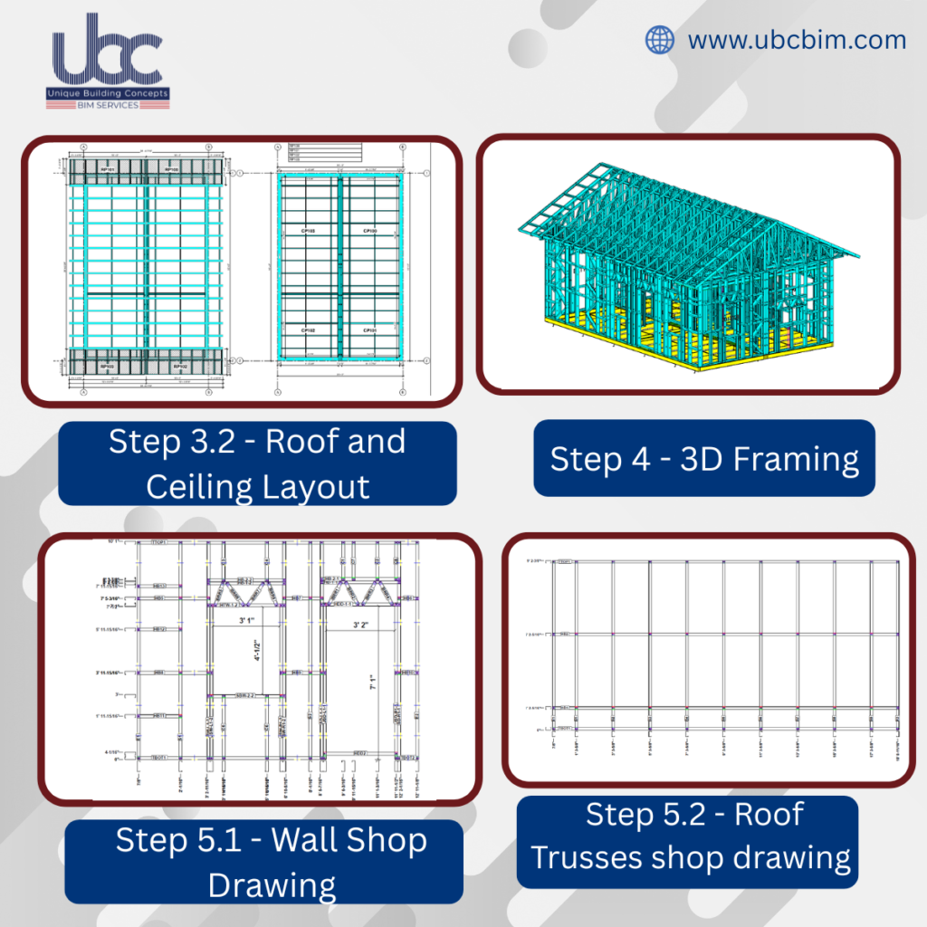
Inside the two 300-sq-ft modules, the floor system is engineered with high-tensile steel C-sections. Using Autodesk Revit and MWF, we modelled a reinforced “marriage line” where the two units meet. These beams are designed to be bolted back-to-back, creating a central structural spine that resists racking during transport and ensures a seamless, level floor once joined.
4. The Shared Gable Roof
Designing a gable roof across two separate modules requires high precision.
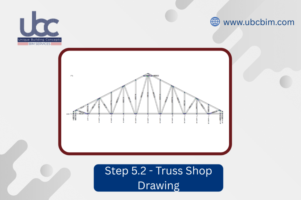
The Engineering: Because the roof is a classic peak, the connection point where the two units meet must be perfect. Using Autodesk Revit and MWF Advance Steel, we modelled every steel truss to ensure that when the modules are bolted together on-site, the roofline is seamless and weather-tight.
5. Faster from Start to Finish
Because the engineering and “Permit Sets” (the technical drawings for the city) are done digitally, we save weeks of time.
No On-Site Waste: Everything is pre-calculated.
Conclusion:
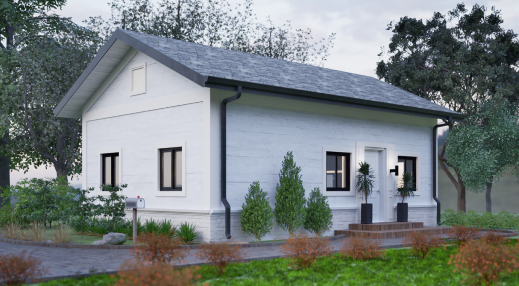
This 600-square-foot modular project demonstrates the power of precision engineering. By utilizing Autodesk Revit and MWF, we developed a digital twin that translates directly into FrameCAD CNC production files.The technical core features a concrete stem wall paired with LGS floor beams, ensuring a rigid, non-deflective foundation. We engineered a reinforced “marriage line” using back-to-back steel profiles to seamlessly join the two units under a shared gable roof. With CNC-punched service holes and sub-millimetre anchor bolt alignment, this workflow eliminates onsite errors, delivering a high-performance, two-bedroom home with the structural integrity of a permanent steel building. UBC offers permit sets, pre-bid packages with 3D BIM model along with bill of materials for project cost estimation, modelling and detailing services, engineering calculations for light gauge steel/cold formed steel/ timber framed building structures in California, USA
Are you looking for a smarter way to build?
From 3D modelling to the final production files, we handle the technical details so you can focus on moving in.